Taxiway design Turning Radius where R is the radius of curve in m V is ther speed in kmph and f is the coefficint of friction between the tyre and pavement surface the value of f may be assumed as 013. Airport Staircase Elevation and Reinforcement Details CAD Template DWG.

Pdf Airport Layout Plan For Efficient Airport Design
Airport pavement design 9.

. Runway Signs and Taxiway Guidance Signs type legend face face sign sign power consumption W legs legs height height length height length black legend white legend mode 2 mode 3 mm mm mm mm mm yellow background red background 322 kph 483 kph FL09060 300 600 900 668 968 12 23 2 2. Runway design 6. Minimum radii of fillet is dependent on The.
REDIM is a computer model developed to locate and design high-speed runway and right angle exits at airports. For aircraft with a CMG and MGW combination in the TDG 2 category use the ADG and TDG Classification Tool below to calculate TDG 2A and 2B. Runway Friction Surveys During Winter Operations.
Taxiways are differentiated by being bordered by blue lights or by having green centre lights depending on the width of the taxiway and the complexity of the taxi pattern. The project included coordination with the watershed district environmental land acquisition and staging issues. Taxiway centerline to parallel taxiwaytaxilane centerline equals 12 times airplane wingspan plus 10 feet.
Bypass taxiway Entrance Taxiway 9302011 AC1505300-13 CHG17 Chap 4 45 C RUNWAY C TAXIWAY L L C TAXIWAYL C TAXIWAYL C RUNWAYL C TAXIWAYL L Figure 4-7. The model uses kinematic equations to characterize the aircraft landing. Minimize the closure time of taxiway c and taxiway g.
Soft Ground Arrestor System. For airport serving large subsonic jet transports minimum value of redius of curvature is 120 m whatever be the speed. The standards for the taxiway design and construction will therefore not be as rigorous as for the runway.
Download Ebook Epub Textbook quickly and easily or read online full books anytime and anywhere. FAA designed software tools like FAARFIELD 25 F806FAAxls and LEDFAA 13 were used to do the design of structural airfield pavement. Automated FOD Detection System Evaluation.
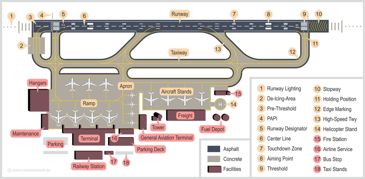
EB-75 AC 1503500-13A Ch1. C RUNWAY C TAXIWAY L L Figure 4-5. Geometric Design Standards Length of taxiway Width of taxiway Width of safety area Longitudinal gradient Transverse gradient Rate of change of longitudinal gradient Sight distance Turning radius 4.
Heliports and stolports appendix. RUNWAY DESIGN Standards RUNWAY DESIGN Runway Design Standards Guidance provided in Chapter 3 of FAA AC 1505300-13A Also in ICAO Annex 14 Aerodrome Design and Operation Used to determine physical dimensions for. Airport Safety Surveillance Sensors.
Runway Edge Light Systems HIRLMIRLLIRL. In addition to displaying pavement dimensions on the users computer screen the program creates a CAD drawing in DXF format that virtually any CAD softwarecan import. 0388𝑊² R 05𝑇𝑆 Where R radius of taxiway m W wheel base of aircraft m T width of taxiway pavement m S distance between point midway of main gear and edge of taxiway pavement m S 6 wheel thread2 Fillets This is extra wide area provided at the curves so that rear wheel does not go off the pavement edge.
Geometric Standard for Taxiway Following eight elements of the geometric standards for Length of taxiway. Optimize taxiway flows to limit the amount of runway crossings. Taxiway centerline to fixed or movable object equals 07 times airplane wingspan plus 10 feet.
It is located at the far end of the intersection. Brian Meyer was Team Leader and Project Manager for numerous environmental planning design and construction projects including the 1 million drainage and safety area improvements project. Runways Runway Shoulders and Blast Pads Runway Safety Areas Runway Object Free Areas RUNWAY DESIGN.
This tool is accurate only when the airplane is aligned with the taxiway centerline when entering the turn. Airport Runway Taxiway and Ramp Design by. AVM 3202 AIRPORT DESIGN.
Visual aids 11. Runway Surface Safety Technology. Taxilane centerline to fixed or movable object equals 06 times airplane wingspan plus 10 feet.
Runway Taxiway Improvements. The phase 3 construction is delineated to. UAS Integration at Airports.
UNIT IV AIRPORT DESIGN CE6604 notes. Removals within taxiway c object free area phase 4 asphalt milling and other removals within taxiway g. Click GET BOOK button and get unlimited access by create free account.
FAA guidelines and ICAO design criteria are strictly followed in the design and orientation of the runway. On precision instrument runways the edge- lighting becomes amber in the last 2000 ft 610 m of the runway or last third of the runway whichever is less. Aviation fuel 8.
Orientation Wind Rose Diagram Runway length Problems on basic and Actual Length Geometric design of runways Configuration and Pavement Design Principles Elements of Taxiway Design Airport Zones Passenger Facilities and Services Runway and Taxiway Markings and lighting. Runway Boundry Sign This sign faces the runway and is visible to pilots exiting the runway. TOP 10 Websites to Download CAD DWG Files.
On instrument runways the white lights change to yellow during last 2000 feet or half the runway length whichever is less and then they turn red as the aircraft reaches the end of the runway. The length of a taxiway depends upon the distance. Alternative Methods to De-ice Runways.
Planning and design of terminal area 5. Airport Antenna Site View Layout CAD Template. AC 1505300-13A Taxiway Fillet Design Tool.
Air traffic control index 20000 buy by rangwala airport engineering edition. Air traffic control 12. Entrance taxiway OUTER COMMON CURVE BYPASS TAXIWAY ENTRANCE TAXIWAY NO TAXIWAY ISLAND C RUNWAY C TAXIWAY L L Figure 4-6.
Airfield pavement Airport Design FAA ICAO Orientation Runway Windrose. This project involved the installation of improvements at an active. Runway and taxiway design notes free download In case you are a admirer of nail artwork but are certainly not accustomed to the various coats of acrylic then this kind of design may just perform nicely to suit your needs.
Taxiway runway intersections should be 90 degrees whenever possible this allows a pilot to have good visibility in both directions before crossing except high-speed exits. The runway edge lights are steady white lights on the edges of the runways. Limit the number of runway crossings.
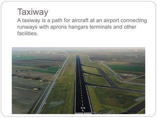
Airport grading and drainage 10. Taxiway Ending Marker This sign indicates the termination of the taxiway. Taxiway A taxiway is a path for aircraft at an airport connecting runways with aprons hangars terminals and other facilities.
32 rows Airport Design Tools. Taxiway design 7. They can be highintensity.
DGR Engineering collaborated with a long-standing airport engineering partner at the Watertown SD Regional Airport to provide electrical design and construction services for the airport including runway and taxiway lights lighted signs and airport electrical systems upgrades. Taxi past this sign to be sure you are clear of the runway. Closed Runway and Taxiway Marking Located at both ends of permanently closed.
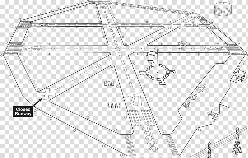
Taxiway f runway 5-23 taxiway c runway 11-29 taxiway anorth taxiway dnorth taxiway asouth runway 11-29.
Airport Engineering Planning Design And Development Of 21st Century Airports By Norman J Ashford Saleh Mumayiz

Design Elements Of Airport Taxiway

Pdf Airport Layout Plan For Efficient Airport Design

Pdf Airport Layout Plan For Efficient Airport Design
Free Download Runway Airport Taxiway Landing Airport Runway Transparent Background Png Clipart Hiclipart
Airport Wikipedia
Taxiway Design
Ppt Taxiway Ae Safitri Nur Wulandari Academia Edu
0 comments
Post a Comment